i'm a hacker in the original meaning of the word: a computer technology enthusiast.
my main focus is backend engineering in all its forms. since 2017, go has been my primary programming language, and i still use it for most of my work.
i started my professional career in 2012. since then, i have worked on many different systems and solved quite a few business and engineering problems along the way.
some of the technologies i have worked with:
javascript and node.js for backends and web applications
c++ for high-load services and embedded systems
gnu/linux for servers and system-level configuration
ansible for keeping this configuration reproducible
mongodb and sql databases for storing all kinds of data
clickhouse for processing millions of metrics and events coming through kafka or rabbitmq
kubernetes, from bare-metal clusters to eks
helm, including the old tiller days
gcp and aws, usually with some attention to keeping the bill under control
jenkins and github actions for automating things i don't want to do manually
and, of course, quite a few other things that accumulated over the years.
this guide is for the lima-linuxboot fork, not upstream Lima. the fork adds VZ linux direct-kernel boot support for macos Monterey.
to install this fork with Homebrew:
brew tap mainnika/lima-linuxboot https://github.com/mainnika/lima-linuxboot
brew install --HEAD mainnika/lima-linuxboot/lima@2-linuxboot
it requires a full Xcode 13 or newer installation to build against a macos 13 SDK.
the problem
macos monterey has Virtualization.framework, but it does not have all of the linux virtual machine APIs that later macos versions have.
the important limitation for me was EFI boot. the regular lima VZ path expects the newer EFI and persistent machine-identifier APIs, so it normally requires macos 13 or newer.
there is another way to boot linux. Virtualization.framework can receive a linux kernel, an initramfs, and a kernel command line directly. this is enough for a normal linux VM, but it means i need to prepare these files myself.
in this post i use an Alpine cloud image and turn it into a small Lima template that boots on an Intel Mac running macos Monterey.
the plan
the Alpine image starts as qcow2 with a partition table. by using direct kernel boot we can use a raw partition image, also direct kernel boot needs the kernel and initramfs as separate files.
the final directory contains:
alpine.ext4
vmlinuz-virt
initramfs-virt
then the Lima template points to all three files:
disk image     -> alpine.ext4
kernel         -> vmlinuz-virt
initramfs      -> initramfs-virt
command line   -> root device, Alpine modules, and console
the important detail is that alpine.ext4 is not the original complete qcow2 disk. it is the root partition copied into a raw file. when VZ attaches it, linux sees that filesystem directly as /dev/vda.
this gives me a plain ext4 filesystem image. it does not contain the original GPT table or the first partition. that is intentional: this file becomes the whole VZ block device, so Linux mounts it as /dev/vda.
extracting the matching kernel and initramfs
the kernel must match the root filesystem. using a random kernel from another Alpine release is an easy way to get a VM that starts but cannot mount its root filesystem.
while the image is still mounted, i copied these files from /boot:
the virt kernel is the useful Alpine kernel here. the initramfs contains the drivers and early userspace needed to find and mount the root filesystem.
getting the kernel command line
direct boot does not run GRUB. that means GRUB does not get a chance to supply the root device, modules, or console settings. i need to take the useful parts of the existing GRUB entry and put them into the Lima template.
linux /boot/vmlinuz-virt root=UUID=53a898f0-60bb-4d47-83a6-8879781b3d34 ro modules=sd-mod,usb-storage,ext4 console=ttyS0,115200n8 console=ttyAMA0,115200n8
i kept the Alpine module list:
modules=sd-mod,usb-storage,ext4
but changed the root device. because i copied the root partition into the whole raw disk image, the root filesystem is /dev/vda, not /dev/vda2 and not the original UUID:
root=/dev/vda rw
finally, VZ exposes the serial console as a virtio console. the useful console argument is:
this example is for an Intel Mac. on Apple silicon, VZ cannot run an x86_64 guest. i need an Alpine aarch64 image and the matching aarch64 kernel and initramfs instead.
also, every fallback item in images needs its own kernel section on Monterey. otherwise Lima could select an EFI-only image after a download fallback, which Monterey cannot boot with VZ.
first boot
i started the instance with:
limactl start --name alpine vz.yaml
the useful thing to watch is the serial log:
tail -f ~/.lima/alpine/serial*.log
a successful boot includes these lines:
[    4.719734] Mounting root: ok.
...
OpenRC 0.63 is starting up Linux 6.18.22-0-virt (x86_64)
...
 * Starting lima-guestagent ... [ ok ]
 * Starting sshd ... [ ok ]
once lima-guestagent and sshd are running, Lima can finish its normal connection setup.
what changes with direct kernel boot
this setup is simple, but it changes who owns the boot configuration.
with EFI boot, GRUB inside the guest chooses the kernel. with direct boot, the Lima template chooses the kernel every time the VM starts.
that means a kernel update inside Alpine does not automatically change the next boot. to update the VM kernel, i need to extract the new matching vmlinuz-virt and initramfs-virt, update the files referenced by the template, and check the command line again. Lima caches these files in the instance directory during creation, so i also recreate the instance after changing the template artifacts.
for macos Monterey this tradeoff is acceptable. it makes the VZ driver useful on an older macos release without needing the newer EFI virtual machine APIs.
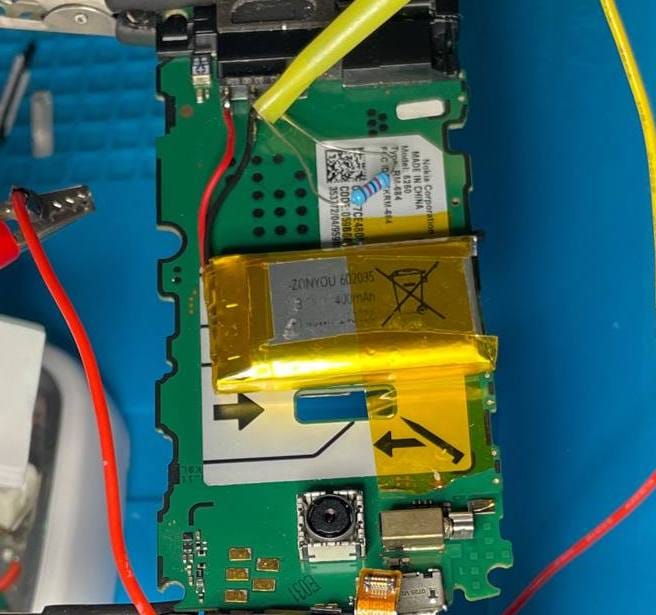
i had a small lipo battery and wanted to use it in an old phone as a replacement for the vendor one.
the battery is:
nominal voltage: 3.7v
capacity: 400mah
max charge current: 1c
max discharge: 5c
for this battery charge:
1c = 400ma
the problem was that the phone did not know about this smaller battery. with an empty battery it tried to charge it at around 600ma.
this is not a dramatic overload for a few seconds, but it is above the battery datasheet limit. for a small lipo inside a phone body i do not want to rely on “probably fine”.
the goal was simple:
- limit charging current to below 400ma
- do not limit discharge current too much
- do not break the phone's battery detection
the basic problem
the phone connects to the battery through the usual battery contacts:
phone bat+
phone bat-
bsi / ntc / battery id
the charging controller is inside the phone. i did not want to replace it. i only wanted to insert something in series with the battery positive wire.
the important detail is that the current direction changes.
during discharge:
lipo -> phone
during charging:
phone -> lipo
so a simple resistor in series with the battery would limit both directions. that would limit charging, but it would also create voltage sag when the phone takes current from the battery.
that is not ideal.
the better idea
the better idea is to split the path into two parallel branches:
one branch for discharge
one branch for charging
the discharge branch should have low voltage drop. the charging branch should limit the current.
if i put a resistor or diode in the battery negative wire, the real battery ground would move relative to the phone ground. that could confuse the charger, battery voltage measurement, temperature sensing, or battery identification.
choosing the resistor
the phone originally tried to charge the empty battery at about 600ma,
the battery limit is 400ma,
i wanted the charging current to be safely below that.
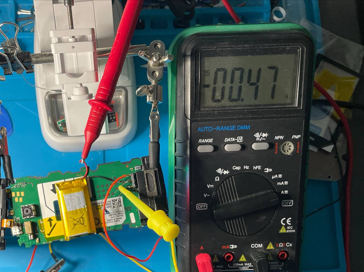
i tested:
Rcharge = 1.5Ω
with this resistor, the charging current became around 200ma:
for a 400mah battery this is:
200ma / 400mah = 0.5c
that is a gentle charge current.
the voltage drop on the resistor at 200ma is:
V = I × R
V = 0.2a × 1.5Ω
V = 0.3v
the resistor power at 200ma is:
P = I² × R
P = 0.2² × 1.5
P = 0.06w
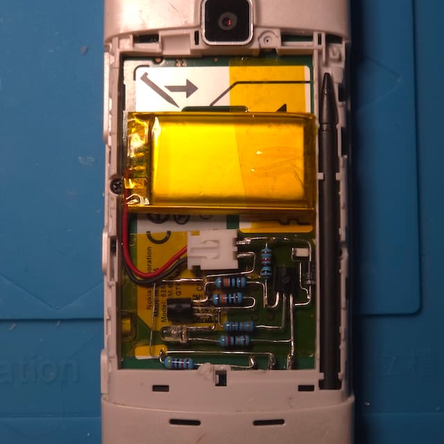
even a small resistor would survive this, but i used a larger power rating because this is inside a phone and i do not want a hot part near the battery.
a 1w resistor is a good comfortable choice. i didn't have one in a pocket but instead i found an old broken charger and there were some SMD 1w resistors inside.
if the current were 400ma, the resistor would dissipate:
even better i'd implement an ideal diode / reverse-blocking power switch, but for a small test setup the 1n5819 worked as the discharge bypass.
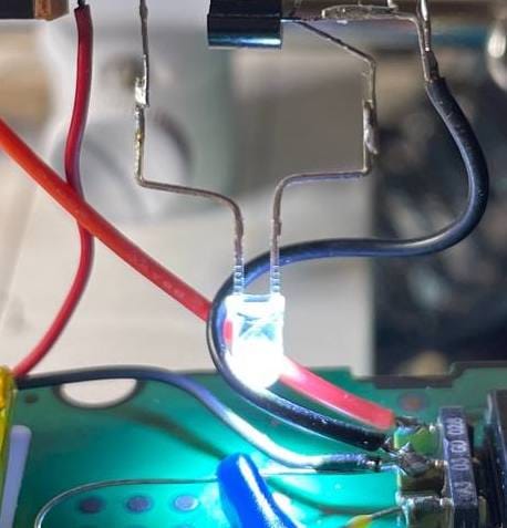
led indicator
i also wanted a led indicator.
there are two different things a led can show:
charger is connected
or:
battery is actually receiving charge current
these are not the same.
the easy version is just:
5V charger pin ── resistor ── LED ── GND
this shows that external charging power is present.
but it does not prove that current is going into the battery.
to detect real battery charge current, i need to detect the voltage drop across the 1.5Ω resistor.
at 200ma the drop is:
0.2a × 1.5Ω = 0.3v
this is too small for a normal silicon transistor to detect directly. a transistor like s9014, s9013, c945, c1815, s8050, a733, a1015, s9015, 2n3906 and similar parts usually needs around 0.6v to 0.7v between base and emitter to open clearly.
so a single normal transistor is not enough.
a comparator would be the clean solution but i dont have one available.
i considered a rough two-transistor indicator without a comparator.
one possible experimental circuit uses:
Q1: A733 PNP
Q2: S9014 / C945 / C1815 NPN
Q1 senses that Phone BAT+ is slightly higher than LiPo+ during charging. Q2 drives the led.
the rough idea is:
                         Q1 A733 PNP
Phone BAT+ ───────────── E
                         B ────── SENSE
                         C ── R3 33kΩ ── B Q2

LiPo+ ─── P1 10kΩ ─── SENSE
SENSE ─── R2 100kΩ ── GND / LiPo-

Q2 S9014 NPN:
B ─── R3 ── C Q1
B ─── R4 100kΩ ─── GND
E ───────────────── GND
C ───────────────── LED-

Phone BAT+ ─── Rled ─── LED+
this is not a precision circuit. it depends on transistor gain, temperature, battery voltage, and resistor values. but for a simple “something is charging” indicator it may be enough after adjustment.
safety checks
after building the circuit, the important measurements are:
charge current into the lipo
voltage directly on the lipo
temperature of the lipo
temperature of the resistor and diode
phone stability during discharge
the current must be measured in the battery path, not only at the usb input, because the phone itself consumes some current too.
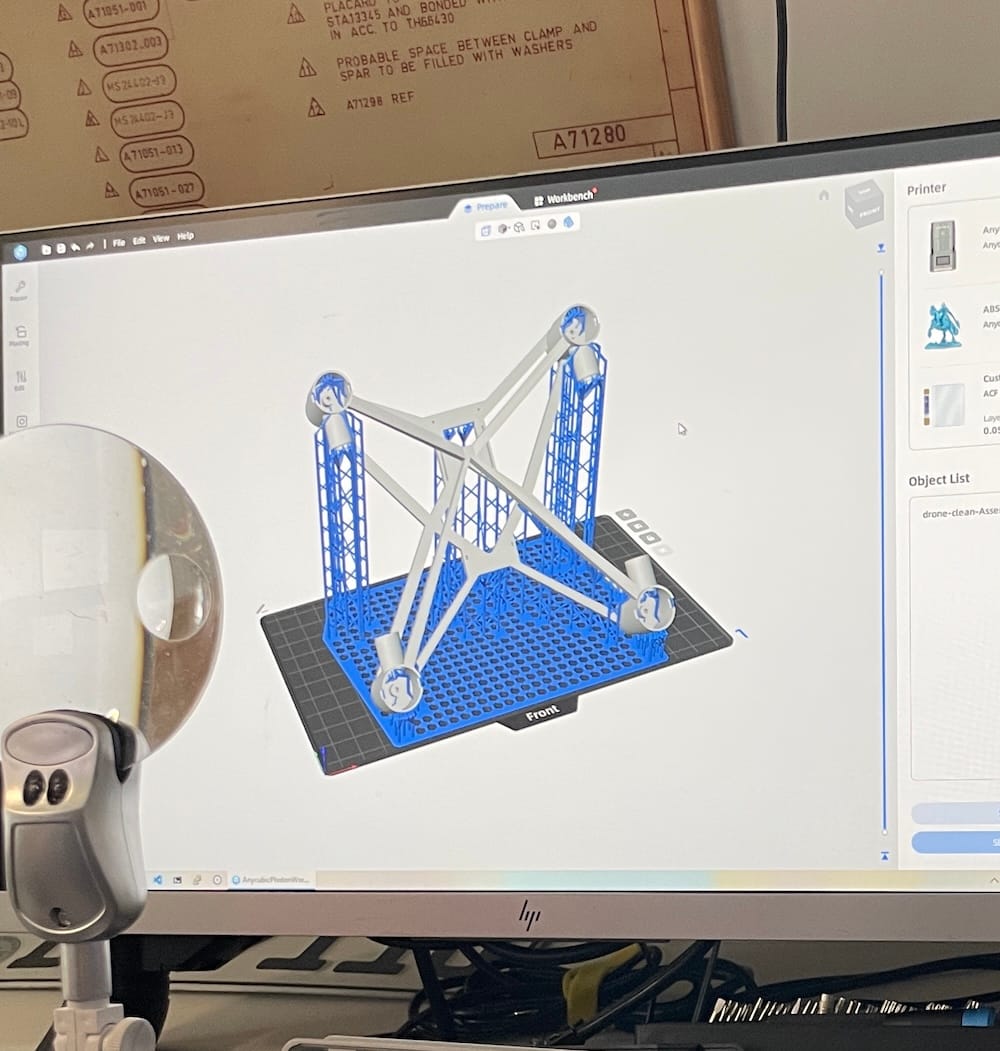
i have a small toy quadcopter. it was not bad, but the original plastic frame had too many unnecessary parts and the flight time was not very interesting.
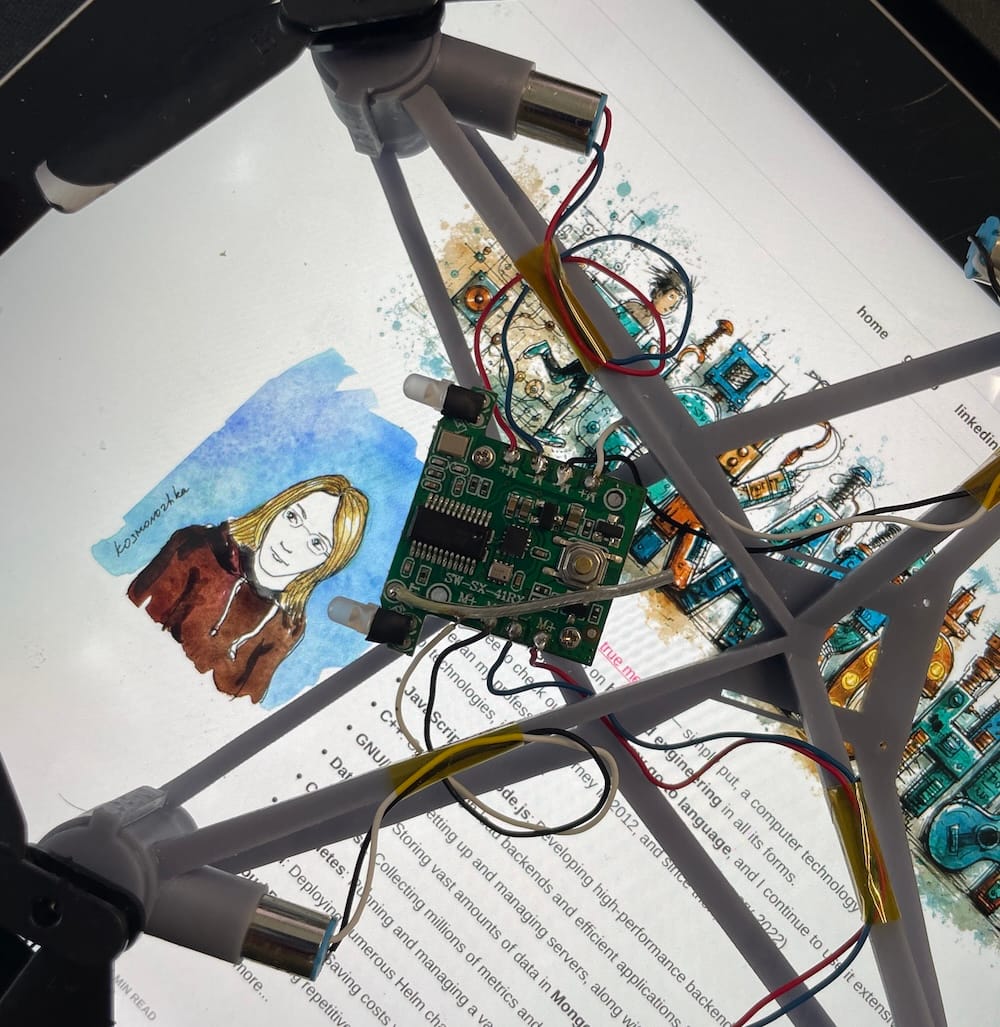
so i decided to use it as a small hardware experiment.
i removed the original frame and other plastic parts, designed my own frame, and printed it. after putting the electronics, motors, propellers, and the original battery back onto the new frame, the total weight became:
47g
the original toy quadcopter was:
59g
so the custom frame version saved:
59g - 47g = 12g
for such a small drone, 12g is a lot.
after that the next obvious question was: if the drone is now lighter, can i use the saved weight for a bigger battery?
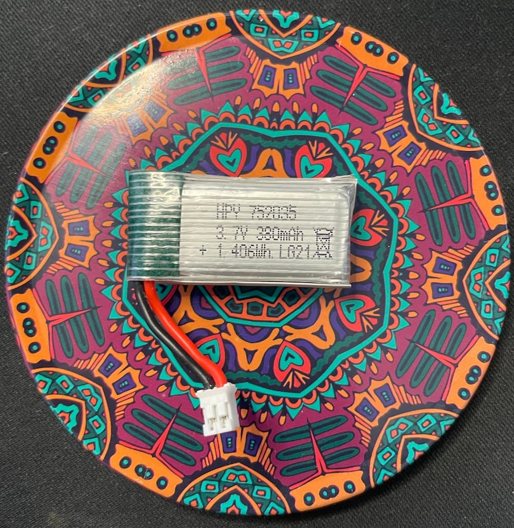
original battery
the original battery is marked as:
HPY 752035
3.7V
380mAh
1.41Wh
it is a 1s lipo battery. 3.7v is the nominal voltage, not the full charge voltage.
for a 1s lipo:
nominal voltage: 3.7V
full charge voltage: 4.20V
the test document for this battery lists it as a polymer lithium-ion battery with:
this is useful because it shows that the original battery is not just a random small lithium cell. it is a high-rate lipo made for a drone.
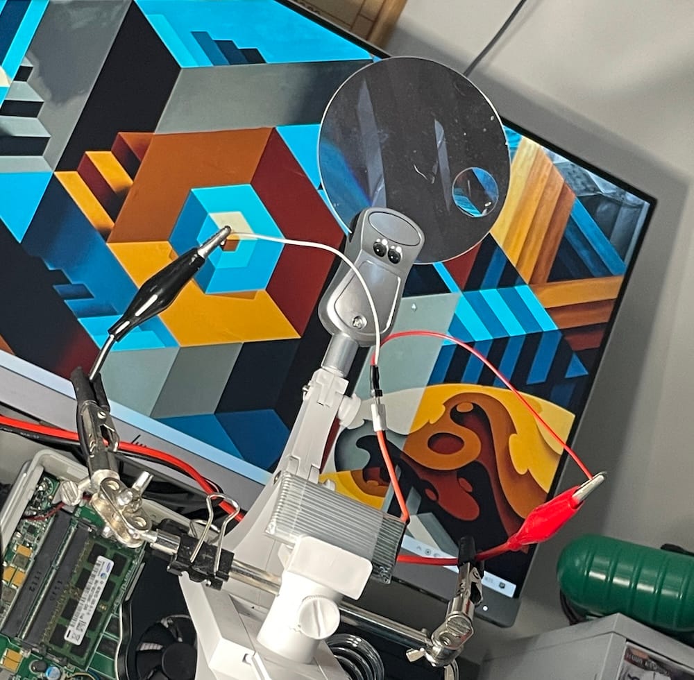
charging it from a laboratory power supply
before changing the battery, i wanted to understand how to charge the original one safely.
with a laboratory power supply, the correct mode is cc/cv:
cc = constant current
cv = constant voltage
the settings are:
voltage: 4.20V
current limit: chosen charging current
for a slow and safe charge, the standard current from the test document is:
76mA
but i first used:
200mA
for a 380mah battery this is:
200mA / 380mAh = 0.53C
so 200ma is not extreme. it is more than the standard current, but far below the listed maximum.
then i also thought about 500ma:
500mA / 380mAh = 1.3C
this is still below the documented max charge current, but i would not use it as my default with a lab power supply. the battery may support it, but fast charging is not the same as gentle charging.
my practical charging settings are:
4.20V
200mA current limit
stop when current drops to around 8-10mA
the important part is not to go above 4.20v.
with a lab power supply there is no smart lipo charger logic. it will not really "finish" the charge for me. i need to stop it when the voltage is at 4.20v and the current has fallen close to the cutoff current.
why the battery current rating is so high
the max charging current in the document looks very high:
1900mA
for a 380mah battery this is:
1900mA / 380mAh = 5C
and the max discharge current is even higher:
7600mA / 380mAh = 20C
this makes sense for a drone battery.
small quadcopters need short bursts of high current. motors do not behave like a small led or a microcontroller board. when the drone climbs, corrects position, or recovers from movement, the motors can pull several amps.
that is also why replacing the battery with an ordinary li-ion cell is a bad idea.
a normal li-ion cell may have the same voltage and even more capacity, but if it cannot provide enough current, the voltage will sag. the drone may become weak, reset the controller, trigger low battery mode early, or overheat the cell.
so for this experiment i only considered 1s lipo drone batteries.
weight after the custom frame
the rebuilt drone weighs:
47g with original battery
the original battery weighs:
9.60g
so the drone without battery is:
47g - 9.60g = 37.4g
this number is the base for all battery calculations.
custom frame without battery: 37.4g
now i can compare battery options.
option 1: 1600mah battery
the first tempting option was a much larger battery:
1600mAh
43g
the total weight would become:
37.4g + 43g = 80.4g
so the drone would be:
80.4g total
compared to the original toy quadcopter:
80.4g - 59g = 21.4g heavier
that is about:
21.4g / 59g = 36% heavier than stock
compared to my custom frame with the original battery:
80.4g - 47g = 33.4g heavier
that is about:
33.4g / 47g = 71% heavier
the battery capacity increase looks great:
1600mAh / 380mAh = 4.2x
but this does not mean the drone will fly 4.2 times longer.
the battery also becomes more than half of the whole aircraft weight:
43g / 80.4g = 53%
at this point the drone becomes almost a flying battery with motors attached.
it may still fly, but the motors will need much more throttle just to hover. the drone will probably become less responsive, and the motors may become hot much faster.
i would test this battery only carefully:
mount it exactly in the center
hover low over something soft
fly for 20-30 seconds
land and check motor temperature
stop if the motors are hot or if hover needs too much throttle
if it hovers at 70-80% throttle, this setup is not good. it means there is not enough thrust reserve.
so the 1600mah battery is interesting, but too extreme for this drone.
option 2: 650mah battery
the second option is much more reasonable:
650mAh
18g
the total weight would become:
37.4g + 18g = 55.4g
this is a very different result.
compared to the original toy quadcopter:
59g - 55.4g = 3.6g lighter
so even with a bigger battery, the drone is still lighter than it was originally.
compared to my custom frame with the original battery:
55.4g - 47g = 8.4g heavier
this is a much smaller penalty.
the capacity increase is:
650mAh / 380mAh = 1.7x
this is not as impressive on paper as 1600mah, but it is much more balanced. the drone should still have a normal thrust-to-weight ratio, and the motors should not suffer as much.
this is exactly the kind of tradeoff that makes sense after rebuilding the frame: use the saved weight for a battery that is larger, but not absurdly larger.
expected flight time
the original battery has:
380mAh
the better replacement candidate has:
650mAh
that is:
1.7x more capacity
because the total drone weight with the 650mah battery is still lower than the original stock weight, the flight time increase may be close to the capacity increase.
if the original flight time was around 5 minutes, i would expect something like:
7-8 minutes
maybe a little more, depending on the motors, propellers, battery quality, and flight style.
with the 1600mah battery the stored energy is much higher, but the extra weight may destroy much of the benefit. the flight time may increase, but the drone will probably become heavy and inefficient.
final comparison
the numbers are:
original toy quadcopter:
59g total

custom printed frame with original battery:
47g total

custom frame without battery:
37.4g

original battery:
380mAh
9.60g

big battery option:
1600mAh
43g
80.4g total

balanced battery option:
650mAh
18g
55.4g total
the 1600mah option gives:
4.2x capacity
but 80.4g total weight
the 650mah option gives:
1.7x capacity
and 55.4g total weight
for this drone, the 650mah battery is the better engineering choice.
conclusion
after rebuilding the quadcopter with my own 3d-printed frame, i saved enough weight to use a better battery.
but the best battery is not the biggest one.
the 1600mah pack is too heavy for this size of drone. it may fly, but it will likely make the quadcopter slow, inefficient, and hard on the motors.
the 650mah pack looks like the sweet spot. it gives noticeably more energy while keeping the total weight below the original stock weight.
so the plan is:
use a 1s 3.7v lipo
keep full charge voltage at 4.20v
check connector polarity
avoid random low-current li-ion cells
use a drone/high-rate lipo
test motor temperature after short flights
choose 650mah instead of 1600mah
this is the nice part of small hardware projects. the final answer is not hidden in a datasheet only. it appears when the numbers, the weight scale, and the real object on the table all agree with each other.
i used to connect my vinyl record player to a speaker manually when i want to listen records.
it was annoying and not practical to touch wires every time, so i decided to use my headless linux server that surprisignly stay nearby as a network audio bridge and listen records through my studio PC.
this article describes how i built an automated analog-to-network pipeline using pipewire, vban, and wireplumber.
hardware setup
the physical setup was straightforward. i connected the audio output of the record player to the line-in jack on the server’s motherboard.
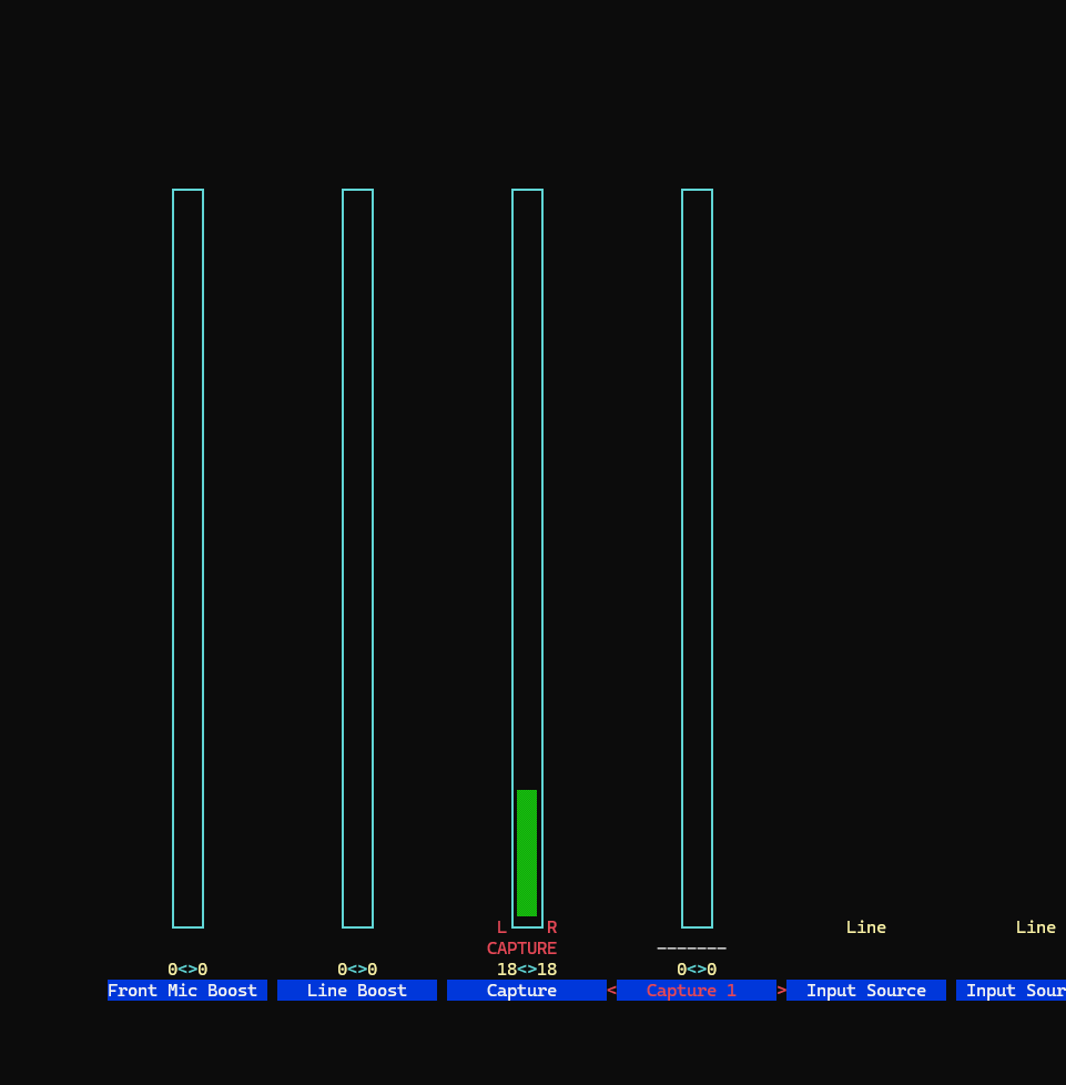
on the linux side i added my user to the audio group to allow access to the sound device and used alsamixer to unmute the capture channel and enable the line-in input.
at this point the server could capture audio from the record player.
phase 1: proof of concept
before automating the entire pipeline, i first confirmed that audio could be transmitted over the network with low latency.
for this experiment i used pipewire together with the vban network protocol.
i created the following configuration file:
~/.config/pipewire/pipewire.conf.d/vban-send.conf
this file loads the libpipewire-module-vban-send module and configures it to send audio packets to my windows pc on port 6980.
this configuration creates a pipewire sink named vban-linein-send. any audio routed into this sink is transmitted as a vban stream.
to test the connection i played an audio file directly into the new sink:
pw-play --target=vban-linein-send test.wav
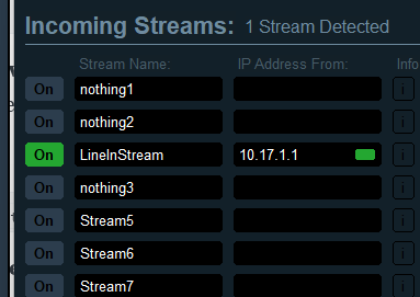
on my windows pc i opened voicemeeter banana, enabled the vban receiver, and configured it to listen for the stream named LineInStream.
the test audio file played through the speakers immediately, confirming that the network connection worked. voicemeeter project is awesome, support them.
understanding the audio graph
pipewire represents audio routing as a graph of connected nodes. once the capture device and the vban sender are active, the signal path looks like this:
vinyl player
     │
     ▼
motherboard line-in
(alsa capture node)
     │
     ▼
pipewire audio graph
     │
     ▼
vban send node
(libpipewire-module-vban-send)
     │
     ▼
udp network stream (through a home network)
     │
     ▼
windows pc (voicemeeter vban receiver)
     │
     ▼
hi-fi speakers
the remaining task was to connect the capture node to the vban node automatically during startup.
phase 2: creating a persistent setup
the goal was to make the system operate automatically. if server reboots, it should capture audio from the line-in port and stream it to the windows machine without manual intervention.
first, i enabled systemd lingering so that pipewire and wireplumber could run without an active login session:
loginctl enable-linger your-username
next, i wrote a wireplumber lua script using objectmanager. the script detects the alsa capture ports and links them to the vban sender ports whenever both are present in the pipewire graph.
while implementing this persistent configuration i encountered two issues.
hurdle 1: line-in gain reset
during the first full test the audio sounded distorted.
the cause was the default line-in gain configured by the motherboard codec. the capture boost was too high for the signal coming from the record player.
lowering the gain in alsamixer removed the distortion. however, after each reboot the gain returned to its original value.
this happens because modern pipewire systems are managed by wireplumber, which applies its own mixer state during startup and overrides alsa settings.
the correct approach was to configure the volume through wireplumber.
first i located the capture device:
wpctl status
then i set the capture level:
wpctl set-volume 48 0.10
wireplumber stores this setting in its state database and reapplies it automatically after each restart.
hurdle 2: the script was not loaded
after solving the volume issue, i placed my lua script in:
this fragment instructs wireplumber to load the script during startup.
after rebooting the server the audio was still silent. investigation showed that the script was not being loaded.
the reason is related to wireplumber’s configuration hierarchy. if the file wireplumber.conf does not exist in the user configuration directory, wireplumber uses the system configuration in /usr/share/wireplumber and ignores user configuration fragments.
the solution was to copy the base configuration file:
once this file existed in the user configuration directory, wireplumber detected the custom fragment and loaded the lua script correctly.
final result
after resolving these issues the system operates automatically.
when the server starts:
pipewire launches in the background
wireplumber restores the capture volume
the vban module initializes
the lua script links the line-in capture ports to the vban sender
from that moment the server continuously transmits the audio signal from the record player to the windows pc in my studio. in voicemeeter i can then route the incoming vinyl stream to any output device, such as the sound bar, the studio hi-fi speakers, or headphones.
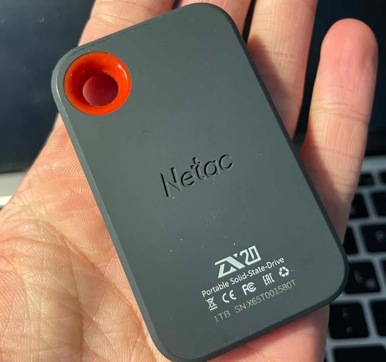
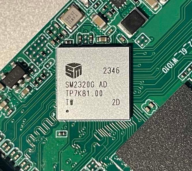
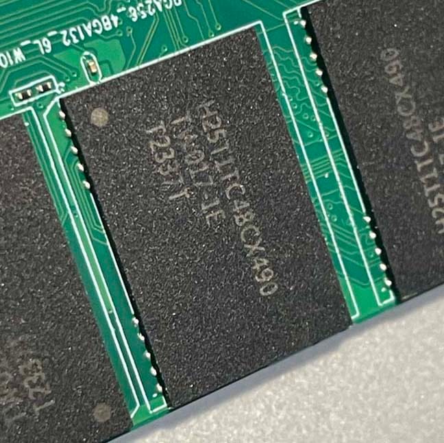
i bought a netac portable ssd (1tb) to use for backups. i use this drive with my linux computer and my samsung android phone, so i formatted it as exfat using the phone.
at first, the drive was very fast. i could copy large files quickly on both devices.
but recently, the speed on linux became very slow. a 300gb backup file that i created months ago now took 3 days to read. the speed was not just slow; it was unstable. the read speed would start normally, then drop to 0 mb/s for several seconds, then start again, and then stop again. it kept freezing and restarting.
i thought the drive was broken, but the problem was actually how the software handles "garbage collection" on the drive. here is how i found the problem and fixed it.
the symptoms
the drive (vendor id 0dd8, product id 2320) connected correctly, but reading files was very difficult.
before: fast reads and writes.
now: reading data (especially small blocks) was very slow.
the main problem: the speed would stop completely (0 mb/s) many times. the drive remained connected, but it paused working.
context: i used the drive with my android phone for months. android writes files correctly, but it does not clean up deleted files on external usb drives.
finding the problem
1. testing the drive
i used a tool called f3probe to test the drive. this tool usually checks for fake drives, but it also measures speed. the results showed the problem:
average write time: 201µs (normal is ~1-10µs)
probe time: 14 minutes (should be less than 10 seconds)
the write time was 200 times slower than normal.
here is why: the ssd was full of "garbage" data. because i used it with my phone for months, i wrote and deleted many files. but android does not send a command called trim to external drives. trim tells the drive which data is deleted and can be erased. without trim, the drive thinks it is 100% full of valid data.
when i tried to read files on linux, the drive's internal controller had to search through all this old data. it became overloaded, paused all work to organize its memory (causing the drop to 0 mb/s), and then started again.
2. the solution: trim
to fix this, the computer must send the trim (or scsi unmap) command. this command cleans the drive.
i tried to run the trim command on linux:
sudo fstrim -v /mnt/usb
# fstrim: the discard operation is not supported
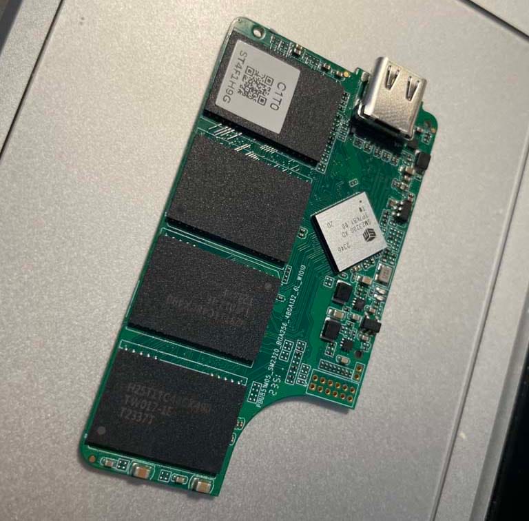
the error message said "not supported." the usb chip inside the netac enclosure was reporting incorrect information to linux. it said it could not do trim, even though the ssd inside could.
the fix: force the unmap command
i had to force linux to ignore the usb chip's report and send the trim command anyway.
step 1: force the setting
i found the device setting in the system files and changed it to unmap.
(note: replace /dev/sda with your correct device name)
# find the specific id for the disk
ls /sys/block/sda/device/scsi_disk/
# output example: 6:0:0:0

# force 'unmap' mode
echo "unmap" | sudo tee /sys/class/scsi_disk/6:0:0:0/provisioning_mode